
 ENG
ENG
 English
 عربى
عربى Español
 中文简体
中文简体Content
- 1 The Central Role of the Fan Shaft in Rotating Machinery Systems
- 2 Material Selection: What Makes a Fan Shaft Truly High-Strength
- 3 Wide Application Across Ventilation, Blowers, Cooling Towers, and Beyond
- 4 Critical Design Features That Separate High-Performance Shafts
- 5 Manufacturing Process and Quality Verification
- 6 Installation, Balancing, and Maintenance Practices That Protect Shaft Life
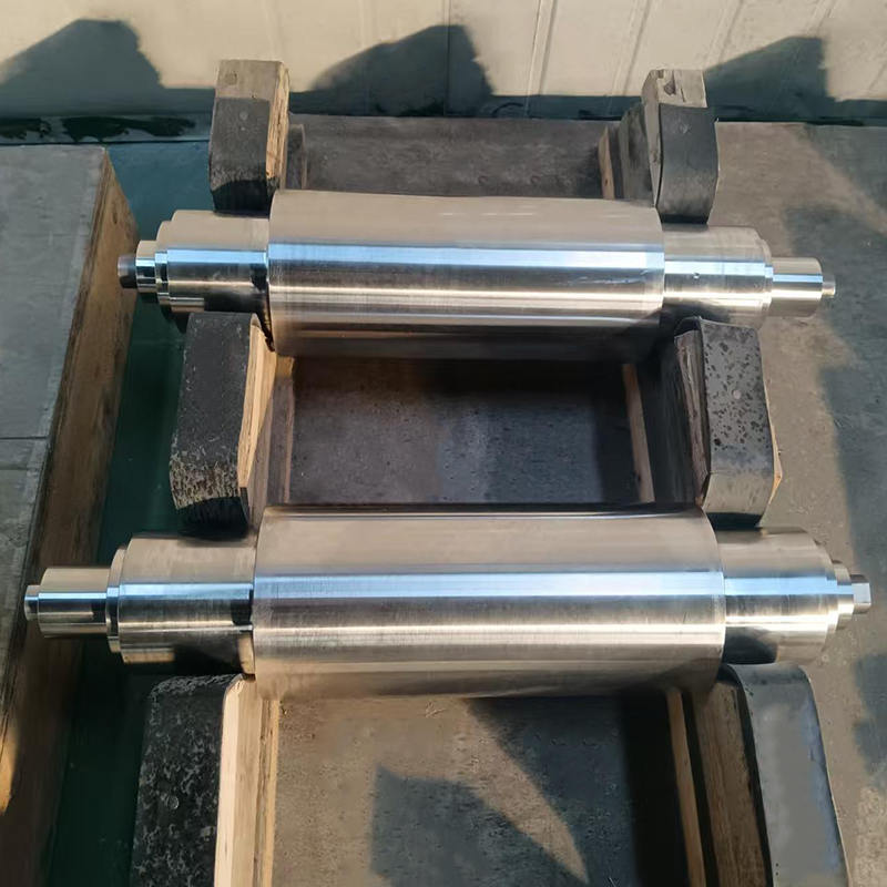
The Central Role of the Fan Shaft in Rotating Machinery Systems
The fan shaft is the mechanical backbone of any rotating air-moving system. Whether the application is an industrial ventilation fan moving air through a factory, a centrifugal blower pressurizing a combustion air supply, a cooling tower fan operating in a permanently humid and corrosive environment, or a large axial fan in a power plant forced-draft system, the shaft is the single component responsible for transmitting torque from the drive source to the impeller while simultaneously supporting the radial and axial loads generated by the rotating assembly. Every revolution of the fan, every variation in load, every thermal cycle, and every vibration event passes through the shaft — making its material quality, dimensional precision, and design integrity the primary determinants of the system's operational reliability and service life.
High-strength fan shafts are engineered specifically to meet the demanding mechanical, thermal, and environmental requirements of these applications. Unlike generic engineering shafts produced to broad dimensional tolerances with standard structural steel, high-strength fan shafts are manufactured from carefully selected alloy steel grades with defined mechanical property requirements, processed through controlled heat treatment to achieve the target strength and toughness balance, and finished to precise dimensional and surface quality standards that ensure correct bearing fit, seal interface, and impeller balance. The difference in service life and operational reliability between a purpose-engineered high-strength fan shaft and a generic substitute is not marginal — it is frequently the difference between years of maintenance-free operation and chronic bearing failures, vibration problems, and unplanned shutdowns.
Material Selection: What Makes a Fan Shaft Truly High-Strength
The term "high-strength" in the context of fan shafts refers to a specific combination of mechanical properties — not simply tensile strength in isolation, but a carefully balanced profile of yield strength, ultimate tensile strength, fatigue endurance limit, toughness, and hardness that together determine how the shaft responds to the complex, time-varying stress states it experiences in service. A shaft that is hard but brittle will crack under impact or shock loads. A shaft that is tough but soft will deflect excessively under the combined weight of a heavy impeller and the aerodynamic forces acting on it, causing bearing misalignment and vibration. The right material achieves both.
Commonly Used Alloy Steel Grades
High-strength fan shafts are most commonly produced from medium-carbon alloy steels in the 40Cr, 42CrMo, 40CrNiMo, and equivalent international grade families. These steels combine carbon content in the range of 0.38% to 0.45% — sufficient to achieve high strength through heat treatment — with chromium, molybdenum, and nickel additions that improve hardenability, allowing full transformation to martensite through the entire cross-section of the shaft during quenching. This through-hardening capability is critical for large-diameter shafts: a steel that hardens only in a shallow surface layer leaves a soft, weak core that provides little resistance to the bending and torsional stresses that act through the shaft's interior.
| Steel Grade | Tensile Strength (MPa) | Yield Strength (MPa) | Typical Application |
| 45 Steel (plain carbon) | 600 – 750 | 355 – 450 | Light-duty, small-diameter fans |
| 40Cr | 900 – 1000 | 750 – 850 | Medium-duty ventilation and blower shafts |
| 42CrMo | 1000 – 1100 | 850 – 950 | Heavy-duty industrial fans, cooling towers |
| 40CrNiMo | 1100 – 1250 | 950 – 1100 | Large power plant fans, high-speed blowers |
| Stainless (316L / 2205 Duplex) | 550 – 800 | 240 – 650 | Corrosive environments, chemical and marine fans |
The selection between these grades is driven by the shaft's diameter, operating speed, transmitted torque, and the criticality of the application. For the largest industrial fan shafts — those driving impellers with diameters of 3 meters or more in power station forced-draft and induced-draft fans — 42CrMo and 40CrNiMo are virtually universal specifications, as the combination of high torque transmission requirements, large shaft cross-sections, and the severe consequences of shaft failure in these critical systems justify the additional material and processing cost.
Wide Application Across Ventilation, Blowers, Cooling Towers, and Beyond
High-strength fan shafts find application across an exceptionally broad range of industrial systems, each presenting its own specific combination of mechanical demands, environmental conditions, and reliability requirements. Understanding the particular stresses of each application context is essential for correct shaft specification.
Industrial Ventilation Systems
Industrial ventilation fans — including axial flow fans for general ventilation, centrifugal fans for process exhaust, and tunnel ventilation jet fans — operate continuously in environments ranging from clean office air to heavily contaminated industrial atmospheres carrying dust, chemical vapors, elevated temperatures, and abrasive particles. The fan shaft in these systems must maintain precise geometric alignment between the drive motor and impeller throughout extended continuous operation, as even small bearing misalignments in continuously running fans generate progressive fatigue damage in both the shaft and bearings. High-strength shafts with sufficient stiffness to minimize elastic deflection under impeller weight and aerodynamic loading are essential for maintaining the bearing alignment accuracy that determines bearing service life.
Industrial Blowers
Centrifugal and roots-type blowers used in combustion air supply, pneumatic conveying, wastewater aeration, and industrial process pressurization systems impose particularly demanding shaft loading conditions. Blowers operate at higher pressures than fans, generating larger aerodynamic forces on the impeller that must be reacted through the shaft and into the bearing system. Additionally, blowers frequently operate at higher rotational speeds than fans of equivalent capacity, increasing the dynamic loads and the sensitivity of the system to shaft unbalance. High-strength fan shafts for blower applications are designed with conservative deflection limits — the shaft must be stiff enough that its natural frequency under combined bending and torsional loading remains well above the operating speed range, preventing resonance conditions that cause catastrophic fatigue failure.
Cooling Tower Fans
Cooling tower fan shafts operate in one of the most challenging environments encountered by any rotating machinery component. They are permanently exposed to high-humidity saturated air, water droplets, water treatment chemicals including biocides and scale inhibitors, and in many installations, airborne contaminants from the facility being cooled. The combination of mechanical stress and aggressive chemical environment creates ideal conditions for corrosion fatigue — a failure mode where corrosion attack on the shaft surface initiates fatigue cracks at stress levels far below the material's normal endurance limit. High-strength cooling tower fan shafts address this through corrosion-resistant material selection, protective surface treatments such as thermal spray coatings or hard chrome plating at critical zones, and design features that eliminate crevice corrosion sites at keyways, interference fits, and seal contact areas.
Power Plant Forced-Draft and Induced-Draft Fans
The largest and most critical fan shaft applications are found in power generation — the forced-draft (FD) and induced-draft (ID) fans that supply combustion air and exhaust flue gas from boiler systems. These fans drive impellers weighing several tonnes at speeds of 500 to 1500 RPM, transmitting tens of thousands of Newton-meters of torque through shafts that may be 200mm to 400mm in diameter and several meters in length. ID fan shafts additionally face elevated temperature exposure from hot flue gas, requiring material selection that retains adequate strength at operating temperatures up to 200°C or higher. Shaft failure in these applications causes immediate boiler shutdown with significant financial and operational consequences, justifying the highest material specifications and the most rigorous manufacturing quality standards.
Critical Design Features That Separate High-Performance Shafts
Beyond material grade, the geometric design of a high-strength fan shaft has profound effects on its fatigue life and reliability. The majority of shaft fatigue failures do not originate in the plain cylindrical sections — they initiate at stress concentration features: keyways, snap ring grooves, cross-drilled holes, abrupt diameter transitions, and interference-fit boundaries. Managing these stress concentrations through thoughtful design is as important as selecting the right steel grade.
- Generous fillet radii at diameter transitions: Shoulder fillets connecting different shaft diameters are primary fatigue initiation sites. High-strength fan shaft designs specify fillet radii as large as the application geometry allows — typically a minimum of 5% to 10% of the smaller shaft diameter — reducing the stress concentration factor from values above 2.5 for sharp corners to below 1.5 for well-designed fillets.
- Keyway design and location: Keyways are unavoidable in most fan shaft designs but create significant stress concentrations. End-milled keyways have stress concentration factors of 2.0 to 3.0; broached keyways with rounded ends are preferred where possible. Keyway locations should be positioned away from high-bending-stress zones — ideally in regions of lower bending moment, such as close to bearing support points rather than mid-span.
- Surface finish at bearing and seal journals: The surface finish at bearing journal diameters is specified to Ra 0.4 to Ra 0.8 micrometers for rolling element bearings and Ra 0.2 to Ra 0.4 micrometers for plain bearings, ensuring correct oil film formation and preventing fretting damage at the bearing-shaft interface that initiates surface fatigue.
- Compressive residual stress introduction: Shot peening or roller burnishing of critical shaft zones — particularly keyway surfaces and fillet radii — introduces compressive residual stresses in the surface layer that must be overcome before fatigue cracks can initiate and propagate. This surface treatment can increase the fatigue life of a shaft section by factors of two to four times at identical nominal stress levels.
- Hollow shaft construction for large diameters: For large-diameter shafts where weight reduction is important — cooling tower fan shafts and large axial fan shafts in particular — hollow construction removes material from the low-stress central zone while retaining the majority of the shaft's bending and torsional stiffness. A hollow shaft with an outer-to-inner diameter ratio of 0.6 retains approximately 87% of the solid shaft's section modulus while reducing weight by 36%.
Manufacturing Process and Quality Verification
The manufacturing process applied to a high-strength fan shaft is as determinative of its final performance as the material specification. The production sequence — from raw material procurement through forging, heat treatment, rough machining, finish machining, and final inspection — must be controlled at each stage to ensure the finished shaft meets its design intent without hidden defects or property variations that could cause premature failure.
Raw material for high-strength fan shafts is typically supplied as hot-forged bar or billet rather than rolled bar, as the forging process refines the grain structure of the steel, closes internal porosity from the solidification process, and aligns the grain flow with the shaft axis to maximize mechanical properties in the primary loading direction. Material certification traceable to the original heat of steel is a minimum requirement for critical applications, providing documented evidence of chemical composition compliance. Ultrasonic testing of the raw material billet prior to machining detects internal flaws — inclusions, pipes, or segregation — that could cause fatigue failure in service without any external indication.
Heat treatment — quenching and tempering to the target hardness range — is performed on the rough-machined blank rather than the final-machined shaft where possible, as the subsequent finish machining removes the potential surface decarburization layer introduced during heat treatment and ensures the precision-machined surfaces are not subjected to quench distortion. Hardness verification at multiple positions across the shaft cross-section confirms through-hardening has been achieved. Final inspection includes dimensional verification of all critical diameters and lengths against drawing tolerances, surface finish measurement at bearing and seal journals, straightness measurement along the shaft axis, and in many critical applications, magnetic particle inspection of all stress concentration features to detect surface and near-surface discontinuities before the shaft enters service.
Installation, Balancing, and Maintenance Practices That Protect Shaft Life
Even a perfectly manufactured high-strength fan shaft will deliver shortened service life if incorrectly installed, inadequately balanced, or poorly maintained in service. The investment in a high-quality shaft is only fully realized when the shaft is treated correctly throughout its operational life.
- Always verify shaft and bearing housing alignment using precision dial indicators or laser alignment systems before commissioning — coupling misalignment generates rotating bending stresses in the shaft that add directly to the design stress and dramatically reduce fatigue life.
- Ensure the impeller and shaft assembly is dynamically balanced to the appropriate ISO 1940 balance grade for the operating speed — typically G2.5 or better for fans operating above 1000 RPM — as residual unbalance generates synchronous rotating forces that are the most common cause of accelerated bearing and shaft fatigue damage.
- Use correct interference fits between the shaft and components such as impeller hubs, bearing inner rings, and couplings — fits that are too loose allow fretting corrosion and micro-movement that initiate fatigue cracks; fits that are too tight create assembly stresses that reduce fatigue life at the interface.
- Monitor vibration levels continuously or at regular intervals using online or portable vibration measurement equipment — a rising vibration trend at running speed frequency indicates developing unbalance from impeller deposit buildup or blade damage, while sub-synchronous or bearing-frequency components can indicate bearing deterioration before it progresses to shaft damage.
- Inspect the shaft surface at keyways, seal contact zones, and any areas showing corrosion or fretting deposits during scheduled maintenance outages, using magnetic particle or dye penetrant inspection methods to detect surface crack initiation before propagation to failure.


")
")
")

")

 TOP
TOP