
 ENG
ENG
 English
 عربى
عربى Español
 中文简体
中文简体Content
- 1 What HVOF Thermal Spray Coating Is and Why It Matters
- 2 The Physics of Supersonic Flame Spraying: How HVOF Works
- 3 Key Coating Properties Achieved by the HVOF Process
- 4 Coating Materials Used in HVOF Thermal Spray
- 5 HVOF vs. Other Thermal Spray and Surface Coating Processes
- 6 Industrial Applications of HVOF Thermal Spray Coating
- 7 Surface Preparation: The Foundation of HVOF Coating Performance
- 8 Process Parameters and Quality Variables in HVOF Coating
- 9 Limitations of the HVOF Coating Process and When to Consider Alternatives
- 10 Selecting a High Velocity Oxygen Fuel Coating Service Provider: Key Criteria
What HVOF Thermal Spray Coating Is and Why It Matters
High Velocity Oxygen Fuel coating -- commonly written as HVOF -- is a thermal spray process that has fundamentally changed the way engineers approach surface protection for high-value industrial components. Where traditional coating methods such as plasma spray or flame spray rely primarily on heat to melt and deposit material, the HVOF coating process uses a combination of extreme velocity and controlled heat to propel powder particles onto a substrate at near-supersonic and supersonic speeds. The result is a coating that is denser, harder, more adherent, and more chemically stable than virtually any other thermal spray alternative.
HVOF thermal spray coating is the process of choice across aerospace, oil and gas, power generation, automotive, and marine industries wherever component surfaces must withstand sustained abrasion, erosion, corrosion, or elevated temperature -- often in combination. Its growing role as a direct replacement for hard chrome plating, which carries severe environmental and health liabilities from hexavalent chromium, has further accelerated its adoption across regulated manufacturing environments globally.
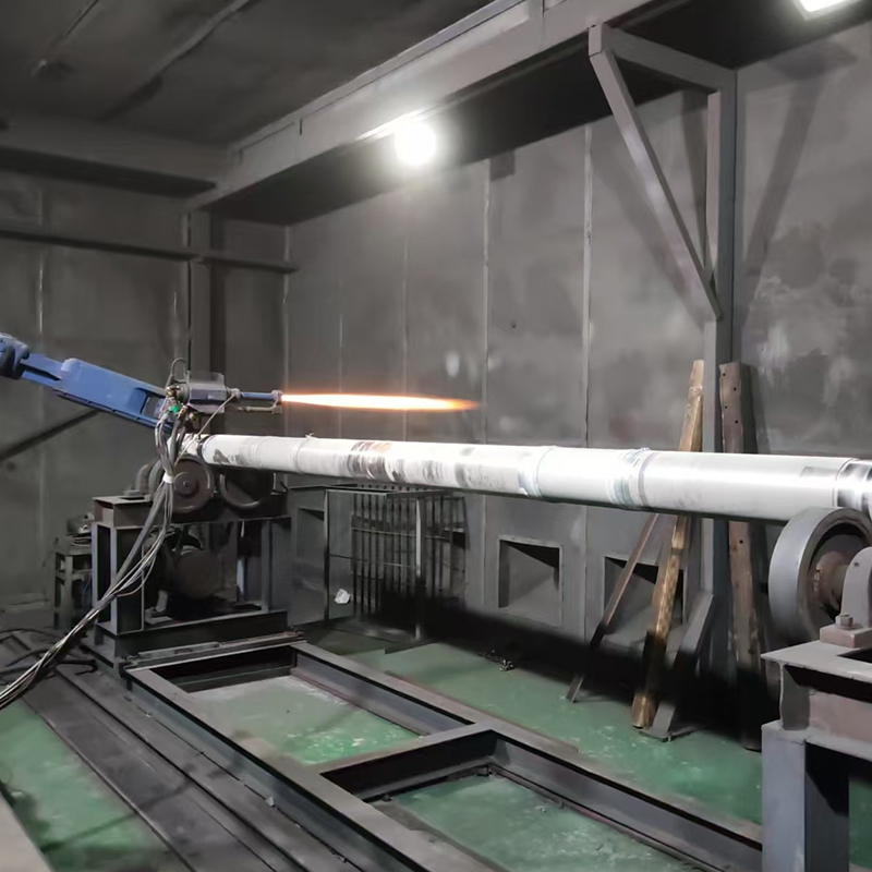
The Physics of Supersonic Flame Spraying: How HVOF Works
Supersonic flame spraying is the descriptive term for what occurs inside an HVOF gun during operation, and understanding the physics of the process is essential for specifying it correctly and troubleshooting coating quality issues. The sequence of events within the gun and at the substrate surface is more precisely engineered than it might initially appear.
Step 1 -- Fuel and Oxygen Combustion
Fuel and oxygen are fed continuously into a water-cooled or air-cooled combustion chamber under high pressure -- typically near 1 MPa (approximately 10 bar). The fuel can be gaseous or liquid. Gas-fuel HVOF systems use propylene, propane, hydrogen, or natural gas. Liquid-fuel HVOF systems use kerosene. The choice of fuel affects flame temperature, coating stress state, and maximum thickness achievable: liquid-fuel systems generally produce compressive coating stresses and higher temperatures, while gas-fuel systems allow thicker coatings to be built up before residual stress causes delamination. Combustion is continuous and sustained, producing a flame temperature of approximately 2,800 degrees Celsius (around 5,000 degrees Fahrenheit).
Step 2 -- Supersonic Gas Jet Generation
The high-pressure combustion products are expelled through a converging-diverging de Laval-type nozzle. This nozzle geometry accelerates the gas stream to supersonic velocities -- the exit velocity at the nozzle ranges from approximately 1,525 to 1,825 metres per second depending on the gun design and fuel selection. This gas velocity is four to five times higher than conventional flame spray processes, which are limited to particle speeds below 150 metres per second. The resulting gas jet carries enormous kinetic energy that is transferred to the powder particles injected into it.
Step 3 -- Powder Injection and Particle Acceleration
Coating feedstock powder -- at a particle size typically in the range of 20 to 50 microns -- is injected into the high-velocity gas stream via a carrier gas (usually nitrogen or argon). The particles are simultaneously heated and accelerated down the barrel of the spray gun. Because the flame temperature of the HVOF process is substantially lower than plasma spray (which operates above 15,000 degrees Celsius), the powder particles are typically brought to a semi-molten or softened state rather than fully liquefied. This is a critical distinction: partial melting preserves the chemical and phase integrity of carbide particles, preventing the decomposition and oxidation that degrade coating properties in higher-temperature processes. Particle velocities at the substrate surface reach 400 to 800 metres per second -- approximately 1,300 to 2,600 feet per second -- in standard HVOF systems, with liquid-fuel variants reaching Mach 2 or above.
Step 4 -- Impact, Deformation, and Coating Formation
When semi-molten particles strike the prepared substrate surface at supersonic velocity, the kinetic energy of the impact causes the particles to deform plastically and spread into thin, overlapping platelets called splats. The mechanical energy of impact is so high that adequate inter-splat bonding is achieved primarily through kinetic deformation rather than through thermal fusion -- the mechanism that governs conventional flame and plasma spray. This kinetic bonding mechanism is what produces HVOF coating's defining characteristics: very low porosity, very low oxide content, and high compressive residual stress at the coating-substrate interface. The coating grows layer by layer as successive passes of the gun build the deposit to the specified thickness, typically between 50 microns and 1 millimetre in finished form.
Step 5 -- Post-Spray Finishing
As-sprayed HVOF coatings have a relatively rough surface finish (Ra values typically in the range of 3 to 6 microns) resulting from the splat morphology and particle size. For most precision engineering applications -- bearings, hydraulic rods, pump shafts -- the coating must be ground and polished to final dimensions and surface finish. Diamond grinding wheels are standard for carbide coatings. Final surface roughness after grinding can reach Ra 0.1 to 0.4 microns, comparable to ground and polished chrome plating. The part temperature must be held below 120 degrees Celsius (approximately 250 degrees Fahrenheit) throughout the spraying cycle to prevent substrate distortion or phase transformation in heat-treated steels.
Key Coating Properties Achieved by the HVOF Process
The combination of supersonic particle velocity and controlled thermal input in the HVOF coating process produces a distinctive property profile that distinguishes it from all other thermal spray methods:
- Porosity below 1 percent: HVOF coatings consistently achieve porosity values below 1 percent by volume, with well-optimised processes reaching below 0.5 percent. This near-zero porosity is the primary reason HVOF coatings provide superior corrosion resistance compared to flame spray or plasma spray, where porosity values of 2 to 5 percent are common. Low porosity eliminates the interconnected void network through which corrosive media can penetrate to the substrate.
- High bond strength exceeding 50 MPa: HVOF coatings routinely achieve adhesive bond strengths greater than 50 MPa (approximately 7,000 psi) to the substrate, with optimised tungsten carbide coatings on properly prepared surfaces exceeding 70 MPa. Bond strength in conventional flame spray or plasma spray is substantially lower, making HVOF the preferred process for components subject to impact, bending, or vibration loads that would delaminate lower-adhesion coatings.
- Oxide content below 1 percent: Because HVOF particle dwell time in the hot gas stream is very short and flame temperature is lower than plasma, oxidation of metal and carbide powders during flight is minimised. Oxide content below 1 percent is typical even for reactive metals, preserving the coating's mechanical toughness and corrosion resistance. High oxide content in coatings applied by other methods degrades both wear performance and corrosion resistance.
- Hardness from 30 to 70 HRC: Depending on the powder selected, HVOF coatings achieve Rockwell C hardness values from 30 to 70. Tungsten carbide-cobalt coatings (WC-Co) achieve hardness at the upper end of this range, delivering wear resistance that exceeds hard chrome plating in most abrasive and erosive environments.
- Compressive residual stress: Unlike plasma spray coatings which typically have tensile residual stress at the substrate interface, HVOF coatings in most configurations develop compressive residual stress. Compressive stress resists crack initiation and propagation, improving coating fatigue life and resistance to spallation under cyclic loading.
- Coating thickness from 50 microns to 1 millimetre: HVOF thermal spray coating is applied at deposition rates of 40 to 200 grams per minute depending on powder type. Finished coating thickness after grinding typically ranges from 0.08 millimetre to 1 millimetre (approximately 0.003 to 0.040 inches), adequate for both dimensional restoration of worn components and new-part protective coating.
Coating Materials Used in HVOF Thermal Spray
The versatility of the HVOF thermal spray process stems partly from the wide range of powder materials it can deposit successfully. Material selection is the primary lever for tuning coating performance to application requirements -- different powders deliver different balances of hardness, toughness, corrosion resistance, and thermal stability.
| Coating Material | Type | Key Properties | Primary Applications |
|---|---|---|---|
| Tungsten Carbide - Cobalt (WC-Co) | Cermet | Highest hardness and wear resistance; excellent bond strength | Pump shafts, compressor rods, landing gear, dies |
| Tungsten Carbide - Cobalt Chrome (WC-CoCr) | Cermet | High wear and corrosion resistance; seawater-grade | Marine shafts, offshore valves, hydraulic cylinders |
| Chromium Carbide - Nickel Chrome (CrC-NiCr) | Cermet | Wear resistance at elevated temperatures up to 900 deg C | Boiler tubes, hot rolls, furnace components, valve stems |
| MCrAlY Alloys (NiCrAlY, CoCrAlY) | Metal alloy | Oxidation resistance; bond coat for thermal barrier coatings | Gas turbine blades, combustion liners |
| Stellite (Cobalt-Chrome Alloys) | Metal alloy | Hardface wear and galling resistance; high toughness | Valve seats, pump impellers, bearing surfaces |
| Nickel and Nickel-Chrome Alloys | Metal alloy | Corrosion resistance; dimensional restoration | Chemical process equipment, worn shaft restoration |
| Alumina and Zirconia Ceramics | Ceramic | Electrical insulation; thermal barrier; chemical inertness | Thermal barrier coatings, electrical insulation components |
Tungsten carbide-cobalt (WC-Co) and its corrosion-resistant variant tungsten carbide-cobalt chrome (WC-CoCr) are the most widely specified high velocity oxygen fuel coating materials globally. Their combination of hardness, toughness, and bond strength makes them the benchmark for shaft and rod protection wherever abrasion, sliding wear, or erosion is the dominant failure mode. The cobalt matrix content -- typically 8 to 17 percent by weight -- governs the balance between hardness and toughness: higher cobalt increases toughness and impact resistance at the cost of some hardness.
HVOF vs. Other Thermal Spray and Surface Coating Processes
Understanding how HVOF thermal spray coating compares to the alternatives it competes with is essential for making the right process selection -- both against other thermal spray variants and against non-spray coating technologies like hard chrome plating.
| Process | Particle Velocity | Porosity | Bond Strength | Oxide Content | Environmental Impact |
|---|---|---|---|---|---|
| HVOF Thermal Spray | 400 to 800 m/s | Below 1 percent | Greater than 50 MPa | Below 1 percent | Low (no toxic waste streams) |
| Plasma Spray (APS) | 200 to 400 m/s | 2 to 5 percent | 20 to 40 MPa | 5 to 15 percent | Low |
| Conventional Flame Spray | Below 150 m/s | 10 to 15 percent | 8 to 20 MPa | 10 to 20 percent | Low |
| Wire Arc Spray | 100 to 150 m/s | 5 to 15 percent | 10 to 30 MPa | 10 to 20 percent | Low |
| Hard Chrome Plating | N/A (electrochemical) | Low (but microcracked) | Molecular bond approx. 240 MPa | N/A | High (hexavalent chromium) |
The comparison with hard chrome plating deserves additional context. Hard chrome plating has a molecular bond strength substantially higher than HVOF on an absolute basis -- approximately 240 MPa compared to 50 to 70 MPa for HVOF. However, hard chrome plating is inherently microcracked as a result of its electrodeposition mechanism, and these microcracks are the initiation sites for corrosion and fatigue failure under cyclic loading. HVOF coatings are crack-free in as-sprayed condition, which compensates for their lower absolute bond strength in most service environments. Combined with the elimination of hexavalent chromium -- a carcinogenic substance subject to tightening environmental regulation in the EU, USA, and globally -- HVOF has become the technically and environmentally superior alternative for the majority of hard chrome replacement applications.
Industrial Applications of HVOF Thermal Spray Coating
HVOF thermal spray coating is applied wherever a component surface must outlast the conditions placed on it in service -- where baseline material properties are insufficient and replacement is more costly than protection. The following industries rely on HVOF coating as standard practice rather than a specialist option:
Aerospace and Aviation
Aerospace is both the most demanding and most mature application environment for HVOF coating. Landing gear components -- outer cylinders, inner barrels, axles -- are coated with WC-CoCr to resist the combined abrasion, corrosion, and impact loads of repeated takeoff and landing cycles. Turbine shafts and compressor components are coated to restore worn dimensions and extend service intervals. MCrAlY bond coats applied by HVOF form the adhesion layer for yttria-stabilised zirconia thermal barrier coatings (TBCs) on turbine blades that operate continuously at temperatures exceeding the melting point of the underlying nickel superalloy substrate. The aerospace qualification process for HVOF coatings is rigorous -- multiple salt spray, fatigue, and adhesion tests are required before a coating specification is approved for flight-critical parts.
Oil, Gas, and Petrochemical
Pump shafts, valve bodies, drill tool components, gate valves, and choke valves in oil and gas service operate in environments that combine abrasive slurry, corrosive brine, and high mechanical stress simultaneously. WC-Co and WC-CoCr HVOF coatings extend component life in these conditions by factors of three to ten compared to uncoated or conventionally coated alternatives. Offshore and subsea applications specify WC-CoCr for its combination of wear and seawater corrosion resistance. HVOF-coated mud rotors used in directional drilling applications have demonstrated service lives two to four times longer than hard chrome plated equivalents in high-chloride downhole environments, with correspondingly lower overall drilling cost per metre.
Power Generation
Boiler tubes in coal and biomass-fired power plants suffer severe erosion from ash particle impingement and corrosion from sulphur compounds at elevated temperatures. CrC-NiCr HVOF coatings provide erosion-corrosion protection at temperatures up to 900 degrees Celsius, dramatically extending tube replacement intervals and reducing forced outage rates. Gas turbine components -- including compressor blades, seal faces, and bearing journals -- are routinely HVOF coated as part of overhaul and refurbishment cycles. The ability to restore worn dimensions precisely through controlled HVOF deposition followed by precision grinding makes it cost-effective to reclaim components that would otherwise require replacement at full new-part cost.
Automotive and Industrial Manufacturing
Piston rings, hydraulic rods, transmission components, and injection moulding screws and barrels are among the automotive and industrial components routinely protected by HVOF coating. Mazda demonstrated the industrial-scale applicability of HVOF technology in the development of its MX-30 e-SKYACTIV R-EV rotary unit, where HVOF coating enabled the transition from cast iron to aluminium for weight reduction while maintaining the surface durability of the original design. In injection moulding and extrusion, high-percentage tungsten carbide HVOF coatings on feedscrews have delivered two to four times greater wear life versus baseline material when processing abrasive glass-fibre and mineral-filled compounds.
Marine and Offshore
Ship propeller shafts, rudder pintles, thruster components, deck crane pins, and mooring system components all operate in permanently wet, salt-laden, and often biologically active environments. WC-CoCr HVOF coatings on shaft liner surfaces achieve porosity below 0.5 percent, sealing the substrate completely against sub-corrosion that would otherwise initiate under a porous ceramic or plasma spray coating. Tests on HVOF-coated shaft liners in marine service have indicated total service lifetimes in excess of 20 years under continuous operation -- a several-fold improvement over ceramic plasma spray alternatives.
Surface Preparation: The Foundation of HVOF Coating Performance
No thermal spray process -- HVOF included -- will deliver its rated coating properties on an inadequately prepared substrate. Because HVOF thermal spray bonding is predominantly mechanical rather than metallurgical, the profile, cleanliness, and chemical state of the substrate surface at the moment of deposition directly control adhesion strength and long-term coating integrity.
The standard surface preparation sequence for HVOF coating is as follows:
- Degreasing: The substrate must be completely free of oils, cutting fluids, and contaminants before grit blasting. Solvent degreasing or alkaline cleaning is standard. Any contamination remaining after degreasing will be embedded into the surface profile during grit blasting and will create adhesion failure sites.
- Grit blasting: The clean surface is grit blasted with aluminium oxide or steel grit to create a roughened anchor profile -- typically Ra 4 to 8 microns. Grit blasting simultaneously removes surface oxides, increases the effective bonding surface area, and induces compressive stress in the near-surface zone. Blasting parameters (grit type, size, pressure, angle, and distance) must be controlled and documented for each substrate material and geometry.
- Post-blast cleaning: Blasted surfaces must be cleaned with dry compressed air -- completely free of oil and moisture contamination from the compressor system -- to remove residual grit and dust. Contaminated blast air is one of the most common causes of adhesion failure in HVOF coating operations.
- Immediate spraying: The blasted and cleaned surface should be sprayed as soon as possible after preparation -- within 4 hours as a standard guideline -- to prevent re-oxidation or moisture adsorption that would degrade the prepared surface condition.
Any surface defects present before coating will be replicated or amplified in the coating, not concealed by it. Pits, grooves, and corrosion damage on the substrate surface must be machined out before grit blasting. Attempting to fill substrate surface defects with HVOF coating material results in inadequately supported coating regions that fail under service loading.
Process Parameters and Quality Variables in HVOF Coating
The quality of an HVOF thermal spray coating is not solely a function of the machine or material -- it is the product of tightly controlled process parameters that must be monitored and documented throughout each coating run. The following variables are the most consequential:
- Fuel-to-oxygen ratio: The stoichiometry of the fuel-oxygen mixture governs flame temperature, combustion completeness, and the oxidising or reducing character of the gas jet. For hydrogen fuel, the optimal ratio is 4:1 to 5:1 (hydrogen to oxygen). For propane, the optimal ratio is 1:4 to 1:5 (propane to oxygen). Lean mixtures (excess oxygen) increase oxide content; rich mixtures (excess fuel) reduce flame temperature and particle velocity, increasing porosity.
- Stand-off distance: The distance from the gun nozzle to the substrate surface -- typically 150 to 380 millimetres depending on the system and material -- controls particle temperature and velocity at impact. Too close and the substrate overheats; too far and particles cool excessively, reducing deformation on impact and increasing porosity. Incorrect stand-off is one of the two most common causes of elevated oxide content in HVOF coatings.
- Powder feed rate: Feed rate of 40 to 200 grams per minute controls deposition rate and coating per pass. Excessive feed rate overloads the flame, reducing particle heating and acceleration and degrading coating density. Insufficient feed rate wastes energy and increases cost per unit thickness without process benefit.
- Substrate temperature control: Part temperature must be monitored continuously throughout the spray cycle and held below 120 degrees Celsius for most steel substrates. Cooling air -- completely oil-free and dry -- is directed at the part between passes. Thermal distortion of precision components and tempering of heat-treated steels are the consequences of inadequate temperature control.
- Coating thickness per pass: A maximum of 0.5 to 1.0 mil (0.013 to 0.025 millimetres) per pass is the standard guideline for most carbide coatings. Exceeding this per-pass thickness increases residual stress accumulation, raising the risk of cracking or delamination before the target thickness is reached.
- Powder particle size distribution: HVOF requires powder particles in the range of 20 to 50 microns with a tight size distribution -- a spread of 20 microns (for example, 30 to 50 microns) is commonly specified. Coarser particles do not heat and accelerate adequately; finer particles overheat and decompose in the high-energy flame, increasing oxide content and degrading coating chemistry.
Limitations of the HVOF Coating Process and When to Consider Alternatives
HVOF thermal spray coating is not universally applicable -- its process characteristics create genuine constraints that must be factored into application engineering decisions:
- Line-of-sight limitation: HVOF is a line-of-sight process -- the spray gun must have direct, unobstructed access to every surface being coated. Internal bores, undercuts, re-entrant geometries, and complex cavities cannot be coated with standard HVOF guns. Specialised internal diameter (ID) HVOF gun configurations extend the process to some bore geometries, but at significantly higher equipment cost and with reduced process window compared to external surface coating.
- Noise and process environment requirements: The HVOF gun operates at very high noise levels -- typically above 130 dB at the gun -- requiring full acoustic enclosure of the spray booth, mandatory hearing protection for all personnel, and extraction ventilation for metallic powder dust and combustion by-products. This infrastructure requirement adds to the capital cost of establishing an HVOF coating facility.
- Skilled operator requirement: Despite increasing automation through robotically controlled spray cells, HVOF coating quality is highly sensitive to operator decisions during setup, parameter monitoring, and quality inspection. Highly trained certified thermal spray technicians are required to maintain consistent coating quality -- a staffing consideration for operations establishing an in-house HVOF capability.
- Substrate temperature sensitivity: Components made from aluminium alloys, magnesium, or polymer-matrix composites require careful management of heat input during HVOF spraying. While HVOF generates less heat than plasma spray, cumulative thermal input across a multi-pass coating cycle can still distort thin-walled or thermally sensitive substrates. Pre-heating and post-cooling strategies must be designed into the process plan for these materials.
- Cost relative to simpler alternatives: For low-wear applications or large surfaces where corrosion resistance rather than hardness is the primary requirement, arc spray or plasma spray may provide adequate performance at significantly lower equipment and consumable cost. HVOF's cost premium over other thermal spray processes is justified only where its superior density, hardness, and bond strength are genuinely required by the application.
Selecting a High Velocity Oxygen Fuel Coating Service Provider: Key Criteria
For organisations procuring high velocity oxygen fuel coating services from an external provider rather than operating in-house, the following criteria separate reliable long-term suppliers from commodity coating shops that may not maintain the process discipline required for critical component applications:
- Certifications and qualifications: Look for providers certified to relevant quality management standards (ISO 9001 minimum; AS9100 for aerospace; NADCAP accreditation for aerospace thermal spray is the global benchmark). NADCAP accreditation specifically requires periodic third-party audits of process controls, equipment calibration, and operator qualification -- it is the most reliable single indicator of thermal spray process discipline.
- Industry-specific experience: Request evidence of coating experience in your specific application sector. A provider with extensive oil-and-gas pump shaft coating experience may not have the aerospace fatigue and adhesion test data required for landing gear qualification. Sector-specific track record matters more than general thermal spray capability.
- In-house testing capability: A quality HVOF coating provider should be able to measure and report porosity (by metallographic cross-section), bond strength (by ASTM C633 adhesion test), coating thickness, and surface roughness as standard deliverables with each production batch. Providers who cannot supply these data points are not operating at the process control level required for critical engineering components.
- Robotic spray cell automation: Robotic HVOF coating cells eliminate the gun-motion variability inherent in manual spraying, producing more consistent coating thickness distribution and better batch-to-batch repeatability. For precision components requiring tight thickness tolerances, a provider operating automated robotic cells is preferable to one relying on manually controlled gun traversal.
- Post-spray machining capability: The ability to grind and polish HVOF coatings in-house, using diamond grinding equipment certified for the required dimensional tolerances, is a significant advantage. External grinding after HVOF coating introduces additional handling, transportation risk, and potential for dimensional error from re-fixtured setups. Providers offering integrated spray-and-grind capability under one quality management system deliver better dimensional control and faster turnaround.
HVOF thermal spray coating is a technology with a well-established performance record spanning four decades of industrial application, but its benefits are fully realised only when every stage -- substrate preparation, powder selection, process parameter control, post-spray finishing, and quality verification -- is executed by personnel who understand what the process demands and what the consequences of each variable are. The difference between an HVOF coating that extends component life by a factor of five and one that fails within weeks of service entry is not in the machine -- it is in the discipline applied at every step of the process chain.


")
")
")

")

 TOP
TOP