
 ENG
ENG
 English
 عربى
عربى Español
 中文简体
中文简体Content
- 1 Wear-Resistant and Coated Tribological Components: Why Surface Engineering Defines Machine Life
- 2 Wear-Resistant Bushing: Design, Materials, and Performance
- 3 Wear-Resistant Plunger: Construction, Coatings, and High-Pressure Applications
- 4 Coated Thrust Plate: Managing Axial Load at Rotating Interfaces
- 5 Coated Shaft Sleeve: Protecting the Shaft at Critical Interface Zones
- 6 Coating Process Selection and Quality Assurance
- 7 Maintenance, Inspection, and Replacement Criteria
Wear-Resistant and Coated Tribological Components: Why Surface Engineering Defines Machine Life
In any mechanical system where two surfaces move relative to each other under load, wear is the dominant failure mechanism that limits service life. Bushings absorb radial load and guide shaft motion. Plungers reciprocate under high pressure. Thrust plates carry axial load at rotating interfaces. Shaft sleeves protect the shaft surface from wear, corrosion, and damage at critical sealing and bearing zones. Each of these components sits at a tribological interface -- a contact zone where friction, wear, and lubrication interact to determine how long the machine operates before maintenance, repair, or replacement is needed.
The engineering response to wear at these interfaces takes two parallel approaches: selecting a substrate material with inherently superior wear resistance, or applying a surface coating or treatment that transforms the tribological properties of a standard substrate material into those required by the application. Wear-resistant bushings and plungers represent the first approach -- the component itself is manufactured from a material or combination of materials chosen for its tribological properties. Coated thrust plates and coated shaft sleeves represent the second -- the bulk material provides mechanical strength and dimensional accuracy while the coating provides the wear resistance, friction control, or corrosion protection that the application demands.
Understanding the design principles, material options, coating technologies, and application requirements behind each of these four component types is the foundation for making informed decisions in machine design, maintenance planning, and component procurement.
Wear-Resistant Bushing: Design, Materials, and Performance
A bushing is a cylindrical sleeve inserted into a bore or housing to provide a bearing surface for a rotating or oscillating shaft or pin. Unlike a rolling element bearing, a bushing is a plain bearing -- it operates through direct sliding contact between the bushing bore and the shaft surface, with performance depending on the tribological properties of the bushing material, the shaft surface finish, and the lubrication conditions at the interface.
Why Wear Resistance Is the Defining Property
The bushing is typically designed as the sacrificial element in the shaft-bushing interface: it wears preferentially, protecting the more expensive or more difficult to replace shaft from surface degradation. This means the bushing must simultaneously be soft enough to conform to minor shaft surface irregularities and distribute load evenly, and hard enough to resist abrasive wear from contamination particles, adhesive wear from metal-to-metal contact during lubricant starvation, and fatigue wear from cyclic loading. The wear-resistant bushing is engineered to navigate this apparent contradiction -- achieving sufficient compliance for load distribution while maintaining the hardness and toughness needed for acceptable service life under the specific load, speed, and lubrication conditions of the application.
Wear-Resistant Bushing Materials
The material selection for a wear-resistant bushing is driven by the load, speed (expressed as a pressure-velocity or PV product), lubrication availability, operating temperature, and chemical environment of the specific application. The principal material categories in commercial use are:
- Bronze and copper alloy bushings: The most widely used bushing material across industrial machinery. Tin bronze (CuSn10 and similar alloys) offers an excellent combination of conformability, wear resistance, and emergency dry-running capability. Lead bronze (CuPb10Sn10 and similar alloys) adds lubrication through the release of lead from the matrix under high-load conditions, improving performance in intermittent or boundary lubrication regimes. Aluminum bronze offers higher strength and better corrosion resistance than tin bronze and is preferred in marine, heavy-load, and chemical processing applications. Phosphor bronze combines good wear resistance with superior spring-like resilience, used in applications requiring some elasticity in the bushing.
- Bimetallic (steel-backed) bushings: A steel backing bonded to a thin layer of bearing alloy -- lead bronze, tin babbitt, or polymer-bonded bearing material -- on the running surface. The steel backing provides structural rigidity and precise dimensional control, while the thin bearing alloy layer provides the tribological surface. This construction combines the load capacity and dimensional stability of steel with the wear and lubrication properties of the bearing alloy, and is the standard for engine bearings, hydraulic pump bushings, and high-load industrial applications.
- Sintered metal (powder metallurgy) bushings: Produced by pressing and sintering metal powder -- typically bronze or iron-based -- to create a porous matrix that is subsequently impregnated with oil. The interconnected pore network acts as an oil reservoir that releases lubricant to the bearing surface during operation and reabsorbs it during rest, providing self-lubrication over extended service intervals without external oil supply. Sintered bronze bushings (to ISO 4381 or equivalent) are widely used in agricultural machinery, electric motors, household appliances, and automotive auxiliary components where maintenance-free operation is required.
- Composite and polymer-lined bushings: A steel or bronze backing lined with a low-friction polymer composite -- typically PTFE with a bronze or mineral filler, acetal, or PEEK (polyether ether ketone) -- on the running surface. PTFE-lined bushings (to ISO 6691 or equivalent, such as the widely known DU bushing construction) provide self-lubrication without oil impregnation, operate effectively without external lubrication in maintenance-free applications, and are resistant to water, most chemicals, and edge loading. They are widely used in automotive suspension and steering joints, construction equipment pivot pins, and industrial linkages.
- Cast iron and grey iron bushings: Used in applications where the graphite content of the iron provides inherent dry lubrication, and where the relatively low cost of iron is a significant factor. Grey iron bushings are suitable for lower-speed, moderate-load applications in agricultural and general industrial machinery.
- Carbide and ceramic bushings: Tungsten carbide, silicon carbide, and aluminum oxide ceramic bushings are specified for extreme abrasion resistance in slurry pumps, drilling equipment, and chemical processing machinery where metallic bushings would be destroyed by the abrasive or corrosive environment in unacceptably short service lives. Carbide and ceramic materials are brittle and require careful installation and housing design to avoid edge loading and impact damage.
PV Limit and Application Sizing
The operating limit of a wear-resistant bushing is conventionally expressed as a maximum allowable PV value -- the product of the bearing pressure P (load divided by projected area in MPa or psi) and the sliding velocity V (in m/s or ft/min) at the bearing surface. The PV product represents the rate of frictional heat generation at the contact, and the maximum PV limit of a bushing material is the threshold above which the frictional heat cannot be dissipated fast enough to prevent temperature rise that would degrade the material, accelerate wear, or cause seizure. Bushing selection requires confirming that the operating PV in the application remains below the maximum allowable PV of the chosen material across all operating conditions, including peak load during starting and reversing.
Wear-Resistant Plunger: Construction, Coatings, and High-Pressure Applications
A plunger is a reciprocating cylindrical component that moves linearly within a cylinder, bore, or housing to displace, pressurize, or control the flow of a fluid. Unlike a piston -- which spans the full bore and is sealed by piston rings -- a plunger seals by precision-fit against the bore bore surface or against a close-fitting packing seal, relying on the plunger's own surface accuracy, hardness, and finish to maintain the sealing function across thousands or millions of stroke cycles.
The wear-resistant plunger is found in high-pressure pumps (water jetting, chemical dosing, hydraulic pumps, pressure testing equipment), hydraulic cylinders, injection molding machines, metering valves, and anywhere that a precision cylindrical element must reciprocate under high contact pressure at the seal interface while maintaining dimensional accuracy throughout its service life.
Wear Mechanisms at the Plunger Surface
The plunger surface experiences several simultaneous wear and degradation mechanisms:
- Abrasive wear from the packing seal: The packing or O-ring seal that contacts the plunger surface continuously rubs against it, gradually removing material from both the seal and the plunger surface. The rate of this abrasive wear is determined by the contact pressure of the seal, the relative hardness of the seal and plunger materials, and the presence or absence of particles in the fluid being sealed.
- Corrosion from the process fluid: In chemical dosing, water jetting, and food and pharmaceutical processing applications, the plunger is exposed to aggressive process fluids that can cause corrosion or chemical attack on the plunger surface. Even small amounts of surface corrosion create roughness that accelerates seal wear and increases leakage past the seal.
- Erosion from entrained particles: In pumping applications handling abrasive slurries or process fluids with suspended solids, particles entrained in the fluid impact and erode the plunger surface as it strokes through the seal zone.
- Fatigue damage from cyclic stress: High-pressure plungers experience tensile and compressive stresses on each stroke cycle. Surface defects, corrosion pits, or abrasive damage can initiate fatigue cracks that propagate through the plunger cross-section, leading to sudden brittle fracture rather than gradual wear -- a catastrophic failure mode in high-pressure systems.
Surface Treatments for Wear-Resistant Plungers
The surface hardness, surface roughness, and corrosion resistance of the plunger surface at the seal contact zone are the three properties that most directly determine plunger service life. A range of surface treatments are applied to plunger substrates (typically medium or high carbon steel, stainless steel, or alloy steel) to achieve the required combination of these properties:
- Hard chrome plating: The traditional and still widely used surface treatment for wear-resistant plungers. Electroplated hard chrome (as distinct from decorative thin chrome) produces a surface hardness of HV 800 to 1,000, very low surface roughness achievable by grinding and polishing after plating, and good corrosion resistance. Chrome-plated plungers are standard in hydraulic cylinders, water jetting, and high-pressure chemical pumps. Environmental regulatory pressure from the hexavalent chromium (Cr VI) compounds used in the electroplating bath has driven development of alternative surface treatments, but hard chrome remains in widespread industrial use.
- High velocity oxygen fuel (HVOF) thermal spray coatings: Tungsten carbide-cobalt (WC-Co) or tungsten carbide-cobalt-chromium (WC-CoCr) coatings applied by HVOF thermal spray achieve hardness of HV 1,100 to 1,400 and significantly better abrasion resistance than hard chrome in applications involving particle erosion or aggressive abrasive seal contact. HVOF coatings have become the leading alternative to hard chrome for wear-resistant plungers in applications requiring superior abrasion resistance, and their use has been driven partly by the transition away from hexavalent chromium plating in environmentally regulated markets.
- Ceramic coatings (plasma spray alumina-titania or chromia): Ceramic oxide coatings applied by plasma spray provide extreme hardness (HV 1,200 to 1,800), good corrosion resistance, and excellent performance in corrosive fluid environments where metallic coatings would be attacked. Ceramic-coated plungers are specified in chemical processing, food and pharmaceutical pumping, and water treatment applications where both abrasion and corrosion resistance are required simultaneously.
- Electroless nickel plating: Deposits a uniform nickel-phosphorus alloy coating by chemical reduction without the thickness variations associated with electroplating. Hardness of HV 450 to 600 as-deposited, increasing to HV 900 to 1,000 after heat treatment. Electroless nickel provides excellent corrosion resistance, uniform coverage of complex geometries, and good adhesion without the environmental concerns of hexavalent chromium processes.
- Nitriding and nitrocarburizing: Case hardening of the plunger surface by diffusion of nitrogen (nitriding) or nitrogen and carbon (nitrocarburizing) at elevated temperature. Produces a compound layer and a diffusion zone in the steel substrate with hardness of HV 600 to 1,200 depending on the process and steel grade. No coating thickness is added (unlike plating or thermal spray), so dimensional changes are minimal. Used in plungers where tight dimensional tolerance must be maintained after surface treatment and where moderate abrasion resistance combined with improved fatigue strength is the requirement.
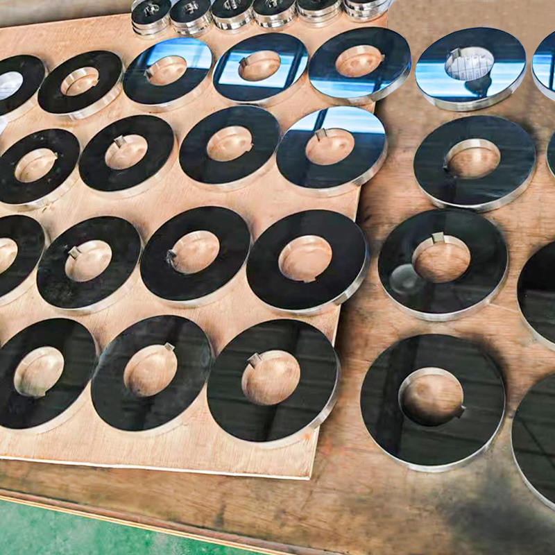
Coated Thrust Plate: Managing Axial Load at Rotating Interfaces
A thrust plate is a flat or annular component that carries axial load at a rotating or oscillating interface -- the load direction is parallel to the axis of rotation, pressing the shaft or rotating element against the plate surface. Thrust plates are found in axial piston pumps and motors (where they form the bearing surface against which the piston slippers slide), in gear boxes (as end-stop bearing elements for gear shafts), in valve assemblies, and in any rotating machine where axial force must be reacted against a fixed surface.
The Tribological Challenge of Thrust Plate Service
The operating conditions at a thrust plate surface are among the most demanding in any plain bearing application. The combination of high contact pressure (axial load divided by the annular contact area), sliding velocity (increasing linearly with radius from the center of the shaft), and the thin oil film that must prevent direct metal-to-metal contact creates a lubrication regime that transitions from hydrodynamic (full film, no contact) at the inner radius to mixed or boundary lubrication (partial or direct contact) at the outer radius where sliding velocity is highest and the oil film tends to be thinnest.
In axial piston hydraulic pumps -- one of the most demanding thrust plate applications -- the swash plate (a form of thrust plate) must carry the full reaction force of the pistons while the rotating cylinder block presses the piston slippers against the swash plate surface at high pressure and speed. The coating on the swash plate directly determines pump efficiency (through friction losses at the slipper-swash plate contact), pump service life, and maximum operating pressure capability.
Coatings Applied to Thrust Plates
The coating on a thrust plate must provide low friction to minimize energy loss, high wear resistance to maintain dimensional accuracy over the service life, and in many applications compatibility with the hydraulic fluid or process fluid environment of the machine:
- PTFE-based polymer coatings: Applied as a bonded solid film lubricant, PTFE coatings on thrust plates provide very low friction coefficients (0.04 to 0.12 in sliding contact) and excellent chemical resistance. Used in food processing, pharmaceutical, and chemical industry thrust applications where lubricant contamination of the process is prohibited and dry or clean-fluid lubrication must be maintained.
- Diamond-like carbon (DLC) coatings: Thin (1 to 5 micron), extremely hard (HV 1,500 to 5,000 depending on the DLC variant) coatings applied by physical vapor deposition (PVD) or plasma-assisted chemical vapor deposition (PACVD). DLC coatings on thrust plates combine very low friction with exceptional wear resistance and smooth surface finish after deposition. Used in high-performance hydraulic pump swash plates, engine components, and precision machinery where both friction reduction and wear life are critical. The low coating thickness means dimensional accuracy of the substrate is preserved.
- Hard chromium and HVOF WC-Co coatings: Applied to thrust plate surfaces requiring a combination of high hardness, good corrosion resistance, and the ability to be precision-ground to flatness after coating. Used in heavy-load industrial machinery and hydraulic components where the coating thickness (20 to 300 microns for HVOF, 20 to 100 microns for hard chrome) provides the wear allowance needed for the design service life.
- Bronze and bimetallic overlays: In axial piston pump swash plates, a thin layer of soft bronze alloy or a bimetal construction (steel body with a bronze or white metal running surface) provides the required combination of conformability (ability to accommodate minor misalignments and surface form errors) and adequate load capacity. The relatively soft bronze surface is sacrificial -- it wears preferentially to the mating slipper surface and can be replaced when worn beyond tolerance.
- Manganese phosphate (Parkerizing): A conversion coating applied to steel thrust plates that creates a microporous iron-manganese phosphate crystal layer that retains oil and reduces initial break-in wear. Not a wear-resistant coating in the conventional sense, but improves running-in behavior and reduces the risk of galling or seizure during the initial period of operation before the oil film is fully established.
Coated Shaft Sleeve: Protecting the Shaft at Critical Interface Zones
A shaft sleeve is a tubular component fitted over a shaft at a specific location -- typically at a sealing point, a bearing location, or a zone of high wear risk -- to provide a replaceable surface that wears in place of the shaft itself. The sleeve can be removed and replaced when worn, preserving the shaft, which is typically a more complex and expensive component to manufacture or replace.
Coated shaft sleeves take this concept a step further: the sleeve substrate provides the dimensional accuracy, mechanical strength, and fit on the shaft, while a coating applied to the sleeve's outer surface provides the tribological properties (wear resistance, corrosion resistance, low friction) needed at the interface with the seal or bearing.
Primary Zones Where Coated Shaft Sleeves Are Applied
The most critical locations for shaft sleeve application are the mechanical seal contact zone in pumps and compressors, the lip seal or packing contact zone in rotating equipment, and the plain bearing contact zone where a bushing or bearing liner runs directly on the shaft surface. In each of these locations, the shaft surface is subject to concentrated wear and corrosion, and the coated sleeve provides a precision surface engineered for that specific tribological environment.
Pump and Compressor Shaft Sleeves
In centrifugal and positive displacement pumps, the shaft passes through a mechanical seal or packed gland that contacts the shaft (or shaft sleeve) surface to prevent fluid leakage from the pump housing to the atmosphere. The seal contact zone experiences continuous rubbing at the shaft's rotational speed, creating frictional heat and progressive wear of both the seal face and the shaft surface. A coated shaft sleeve localized to the seal contact zone provides the surface hardness, low roughness, and corrosion resistance required for long seal life without requiring the entire shaft to be manufactured from an expensive high-alloy material.
Coatings commonly applied to pump shaft sleeves include hard chrome (the traditional standard), HVOF WC-Co (superior abrasion resistance for pumps handling abrasive fluids), and thermally sprayed ceramic coatings (for maximum corrosion resistance in aggressive chemical service). The outer diameter of the coated sleeve is ground to the precision tolerance and surface roughness specified by the seal manufacturer -- typically Ra 0.2 to 0.8 micrometers for mechanical seal contact surfaces.
Coatings for Shaft Sleeves by Operating Environment
| Coating Type | Hardness (HV) | Typical Thickness | Best Environment | Key Limitation |
|---|---|---|---|---|
| Hard chrome plating | 800 to 1,000 | 20 to 100 microns | General industrial, hydraulic | Hexavalent Cr regulatory restrictions |
| HVOF WC-Co | 1,100 to 1,400 | 100 to 500 microns | Abrasive, particle-laden fluids | Higher cost than chrome; not for strong acids |
| Plasma spray alumina | 1,200 to 1,500 | 150 to 500 microns | Corrosive chemicals, food, pharmaceutical | Brittle; sensitive to impact and edge loading |
| Electroless nickel | 450 to 1,000 | 10 to 75 microns | Corrosive environments, tight tolerance | Lower wear resistance than chrome at equivalent thickness |
| DLC (diamond-like carbon) | 1,500 to 5,000 | 1 to 5 microns | High-precision, low friction, clean service | Very thin; adhesion sensitive; higher cost |
| Nitriding (diffusion case) | 600 to 1,200 | 0.1 to 0.5mm case depth | Fatigue and wear combined; no dimensional change | Requires compatible steel grade; no corrosion protection |
Coating Process Selection and Quality Assurance
Selecting the correct coating for a wear-resistant component requires a systematic evaluation of the tribological demands, the chemical environment, the dimensional tolerance requirements, and the regulatory constraints of the specific application. The following framework covers the key decision points in coating specification and quality verification.
Application Load and Speed
High contact pressure favors harder coatings with high compressive strength -- HVOF WC-Co and hard chrome perform well under high contact stress. Low contact pressure with high sliding speed (high PV from velocity rather than load) favors low-friction coatings such as DLC or PTFE-bonded films that minimize frictional heating. Applications with both high pressure and high speed require coatings that combine high hardness with low intrinsic friction -- DLC coatings are the most effective solution for this demanding combination, albeit at higher cost.
Chemical and Corrosion Environment
The chemical compatibility of the coating with the process fluid or operating environment is a selection criterion that must be verified independently of the mechanical performance requirements. HVOF WC-Co coatings, despite their excellent abrasion resistance, are not suitable for strongly acidic environments where the cobalt binder phase is dissolved, leading to rapid loss of coating integrity. Ceramic coatings (alumina, chromia) are chemically inert in most process environments but are vulnerable to alkaline solutions that slowly etch the oxide surface. Electroless nickel provides good general corrosion resistance but may not meet the requirements of highly oxidizing acid environments where nickel is attacked.
Dimensional Tolerance and Post-Coating Finishing
Thicker coatings (HVOF, hard chrome, plasma spray) require post-coating grinding or lapping to restore the required dimensional tolerance and surface finish. The grinding stock (material removed in post-coating finishing) must be included in the pre-coating diameter of the component, and the minimum coating thickness retained after grinding must still provide the required wear allowance. Thin coatings (DLC, electroless nickel at low thickness) can often be applied to a component that is already machined to near-final dimension, as the coating thickness is small enough that its effect on the final dimension can be accounted for in the pre-coating machine allowance.
Quality Verification
The quality of a coating on a wear-resistant component is verified through a combination of destructive and non-destructive testing methods. Coating thickness is measured by eddy current or magnetic induction testing (for coatings on ferromagnetic substrates) or by X-ray fluorescence (XRF) spectrometry. Hardness is measured by microhardness testing (Vickers or Knoop) on cross-sections of the coated component or on witness pieces coated in the same batch. Bond strength is assessed by pull-off adhesion testing or bend testing. Surface roughness is measured by stylus profilometry on the finished component. Porosity of thermal spray coatings is assessed by metallographic examination of polished cross-sections. For safety-critical applications -- high-pressure plungers, pump shaft sleeves in process industry service, and swash plates in mobile hydraulic systems -- a documented coating specification with defined acceptance criteria for each quality parameter and traceability of each coated component to its processing batch and inspection record is the minimum acceptable quality assurance framework.
Maintenance, Inspection, and Replacement Criteria
Wear-resistant bushings, plungers, thrust plates, and shaft sleeves are maintenance items -- they are designed to wear over a defined service life and must be inspected and replaced before their wear reaches the level where the machine's performance or reliability is compromised. Establishing the inspection interval and the replacement criteria for each component is part of the engineering of the tribological system, not an afterthought.
Bushing Wear Measurement and Replacement
Bushing wear is measured as the increase in radial clearance between the shaft and the bushing bore -- measured by feeler gauge, dial indicator, or bore gauge. The maximum allowable clearance is typically two to three times the original installation clearance for general machinery applications, though this varies significantly with application: in precision positioning mechanisms, the replacement criterion may be a much smaller clearance increase, while in agricultural linkages, larger clearances are accepted before replacement. Worn bushings that remain in service beyond their replacement criterion cause shaft misalignment, increased vibration, and accelerated wear of the shaft and adjacent components.
Plunger Inspection and Replacement
Plunger wear is assessed by measuring the outer diameter at the seal contact zone with a micrometer and comparing to the original specification. The replacement criterion is typically a diameter reduction corresponding to the point at which the packing or seal can no longer maintain an adequate sealing geometry against the worn plunger surface. In high-pressure applications, visual inspection for corrosion pits, surface cracking, or coating delamination is also essential at each maintenance interval, as these surface defects can initiate fatigue failure before dimensional wear reaches the replacement criterion.
Shaft Sleeve and Thrust Plate Assessment
Coated shaft sleeves are inspected for coating thickness reduction (measured on the component surface or by monitoring the outer diameter change from the as-new measurement), coating cracking or delamination (detected visually or by dye penetrant inspection), and corrosion pitting in areas where the coating has been breached. Thrust plates are inspected for surface roughness increase (measured by stylus profilometry), flatness loss (measured by surface plate and feeler gauge), and coating wear-through (visually and by hardness spot testing). Both components should be replaced before the coating is worn through to the substrate, as the transition from coated surface to bare substrate surface typically results in a step change in friction, wear rate, and corrosion behavior that rapidly accelerates damage to the mating component and the machine as a whole.


")
")

")

 TOP
TOP