
 ENG
 English
 عربى
 Español
 中文简体

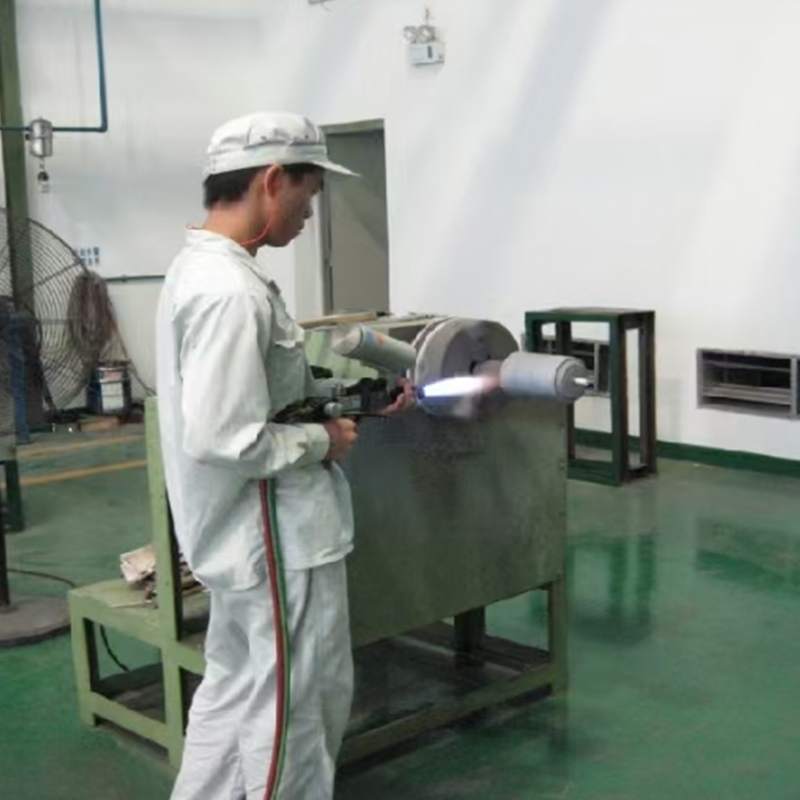
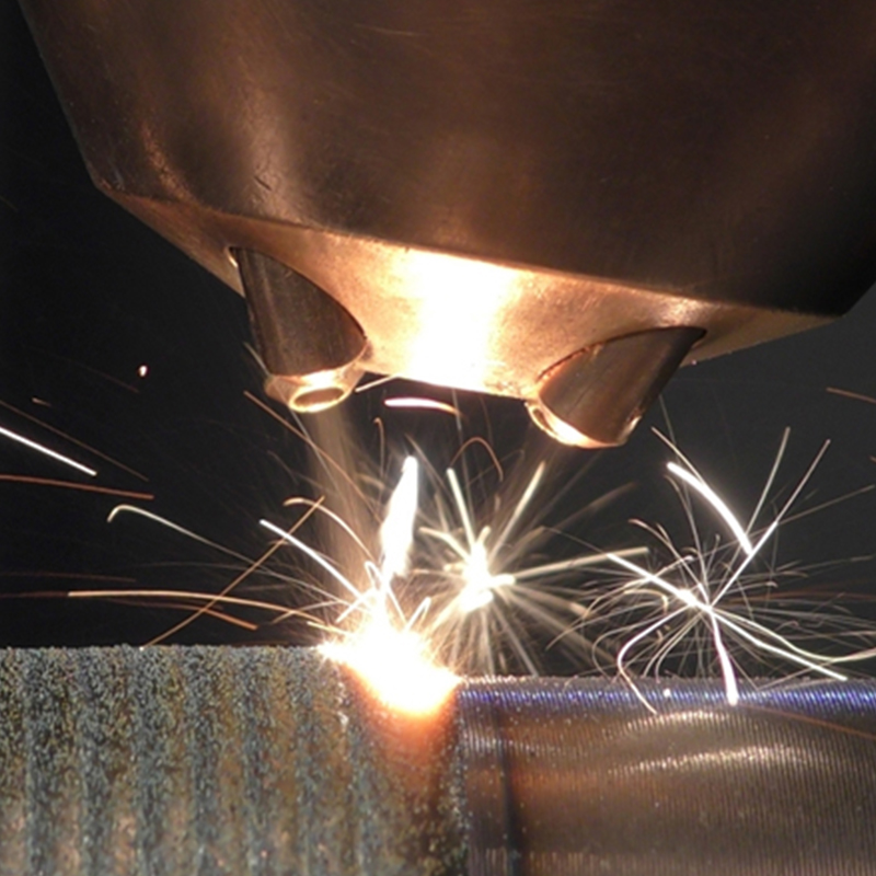
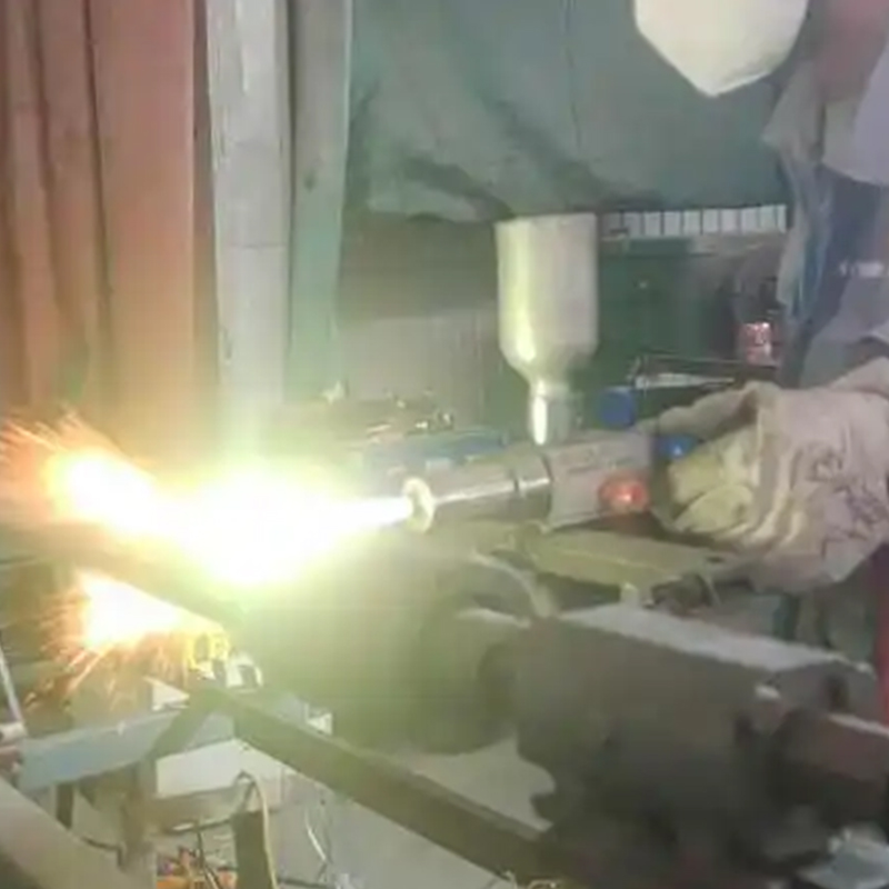
HVOF — high-velocity oxy-fuel spraying — sits at the tougher end of the thermal spray family. Instead of melting wire or powder in a gentle flame, an HVOF gun burns oxygen and fuel in a pressurized chamber and forces the exhaust through a converging-diverging nozzle. The result is a supersonic jet, often above Mach 2, carrying powder particles at 600 to 1000 m/s before they strike the workpiece. Those particles arrive semi-molten rather than fully liquid, flatten into thin overlapping splats, and build a coating that is dense, tightly bonded, and usually in compression rather than tension.
That combination explains why the process keeps turning up wherever a surface has to survive abrasion, erosion, cavitation or sliding contact: pump sleeves, valve trim, hydraulic rods, fan shafts, paper machine rolls. Below we walk through what actually happens in the booth, which parameters really matter, and where HVOF earns its cost — the same things we look at every day when a customer sends us a worn part and a description of what killed it.
Content
- 1 The HVOF Spray Process, Step by Step
- 2 Process Parameters That Decide Coating Quality
- 3 Coatings Commonly Applied with HVOF
- 4 Matching the Coating to the Wear Mode
- 5 Where HVOF Spraying Pays Off
- 6 HVOF Compared with Plasma and Flame Spraying
- 7 Limits and Practical Considerations
- 8 Bringing the Process to Your Parts
The HVOF Spray Process, Step by Step
1. Surface preparation sets the ceiling
Every HVOF coating begins long before the gun fires. Parts are degreased, then grit blasted, usually with angular alumina, to a roughness of roughly Ra 4 to 6 µm. That profile gives the first splats something to grip mechanically. Threads, sealing faces and bearing journals get masked, because a 300 µm layer cannot be removed from a fine thread without damage. We also keep the gap between blasting and spraying short — a freshly blasted surface picks up moisture and dust surprisingly fast.
2. Combustion and gas acceleration
Inside the gun, oxygen and a fuel — kerosene, propane, propylene or hydrogen, depending on the equipment — burn in a pressurized combustion chamber. The hot gas expands through the nozzle and leaves at supersonic speed. Chamber pressure and oxygen-to-fuel ratio are the two levers that set jet velocity and flame temperature, and they are always adjusted together rather than one at a time.
3. Powder injection and in-flight heating
Powder is fed into the jet with a carrier gas, usually nitrogen. Particles in the 15 to 45 µm range are typical. Residence time in the flame is only a few milliseconds, so the powder arrives at the substrate semi-molten. That is exactly what tungsten carbide needs: enough heat to deform on impact, not enough to break down the carbide phase and lose hardness.
4. Impact, splatting and build-up
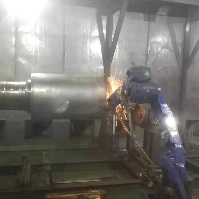
On impact, each particle flattens into a thin disc and solidifies in microseconds, with cooling rates around 10⁶ K/s. The coating builds in passes of 10 to 30 µm while the part rotates on a turntable or the gun travels across it on a robot. Spray distance, part temperature and gun speed are monitored throughout, because drifting part temperature is one of the quietest ways to introduce cracks.
5. Cooling and finishing
Air jets keep the workpiece below roughly 150 to 200 °C between passes. After spraying, coatings are ground, lapped or superfinished to final tolerance. For corrosion duty, a thin polymer sealant is sometimes applied to close the remaining interconnected porosity.
Equipment choice shapes all five steps more than most people expect. A gun with stable combustion and a well-matched nozzle holds a tighter particle-velocity window, which shows up directly in coating density and bond strength.
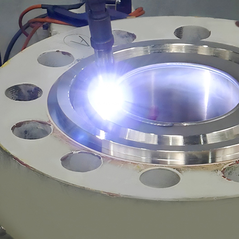
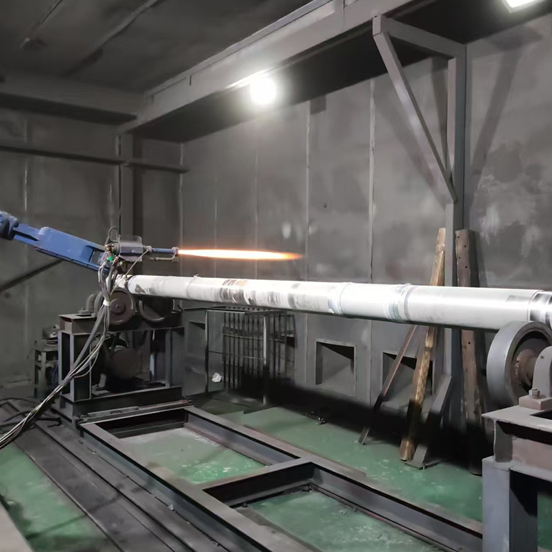 Supersonic HVOF Thermal Spray Coating ServiceHVOF spraying service for metal surfaces, using high particle velocity to produce dense coatings with low porosity and reduced oxidation.View Product →
Process Parameters That Decide Coating Quality
No single number makes a good HVOF coating. The process window is a balance, and every value below shifts when the fuel, powder or part geometry changes. Treat these as starting points for trials, not as fixed rules.
| Parameter | Typical Range | What It Controls |
|---|---|---|
| Oxygen-to-fuel ratio | 1.0–1.3 × stoichiometric | Flame temperature and gas velocity; too rich wastes fuel, too lean overheats carbides |
| Combustion chamber pressure | 0.5–1.0 MPa | Jet speed; higher pressure gives faster particles and denser splats |
| Spray distance | 150–300 mm | Balances in-flight heating against heat input to the substrate |
| Powder feed rate | 30–100 g/min | Thickness per pass and deposition efficiency |
| Particle velocity | 600–1000 m/s | The strongest single predictor of density and bond strength |
| Thickness per pass | 10–30 µm | Keeps residual stress low and limits overheating |
In practice, the parameter that matters most is particle velocity at impact. Faster particles flatten harder, fill voids better and leave the coating in compression. Temperature matters just as much, but in the opposite direction: too much heat and a carbide coating loses the very phase that makes it wear-resistant.
Coatings Commonly Applied with HVOF
The process is closely tied to a small group of materials, each chosen for a specific wear mode:
- Tungsten carbide–cobalt (WC-Co) — the workhorse for abrasion and erosion, from pump sleeves to wire drawing capstans.
- Tungsten carbide–cobalt–chromium (WC-CoCr) — adds corrosion resistance for seawater, slurry and chemical service.
- Chromium carbide–nickel chromium (Cr₃C₂-NiCr) — holds hardness at elevated temperature, common on valve stems and boiler components.
- Nickel-chromium and similar alloys — used where corrosion protection or a ductile bond layer matters more than peak hardness.
- Cobalt-based alloys — for sliding wear and cavitation on hydraulic and marine parts.
Typical finished thickness runs from 100 to 500 µm, depending on the wear allowance and the part's geometry. Below about 50 µm, porosity and substrate influence start to dominate; above roughly 600 µm, residual stress and cost both climb quickly.
Matching the Coating to the Wear Mode
Abrasive wear, corrosion, cavitation and galling call for different answers even when the base part looks identical. A slurry pump impeller exposed to sand wants a thick carbide layer; a valve body handling hot, mildly corrosive media may do better with a carbide-ceramic combination or a chromium carbide layer that keeps its hardness at temperature. Reviewing the failure surface — whether it is scratched, pitted, or eroded in smooth tracks — usually narrows the choice faster than any specification sheet.
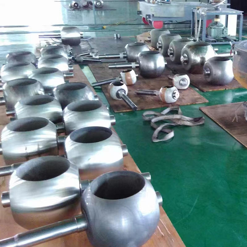 Tungsten Carbide Coated Valve BodyCoated valve body for wear-resistant valve applications, with tungsten carbide, alloy or ceramic options and hardness up to HRC65.View Product →
Where HVOF Spraying Pays Off
The economics work when downtime is expensive and the wear is predictable. Common examples include:
- Pump shafts, sleeves, wear rings and thrust faces in slurry, chemical and boiler feed service
- Plungers, piston rods and valve stems under sliding abrasion
- Butterfly and gate valve bodies, discs and seats in abrasive flow
- Fan shafts, spindles and rolls that must resist erosion without losing balance
- Die casting and stamping tooling that sees heat plus abrasion
- Wire drawing drums, tower wheels and guide rollers
For pump and valve hardware specifically, coating selection usually comes down to how much corrosion accompanies the wear. A pump and valve industry solution overview is often the quickest way to compare coating routes for a given medium and temperature.
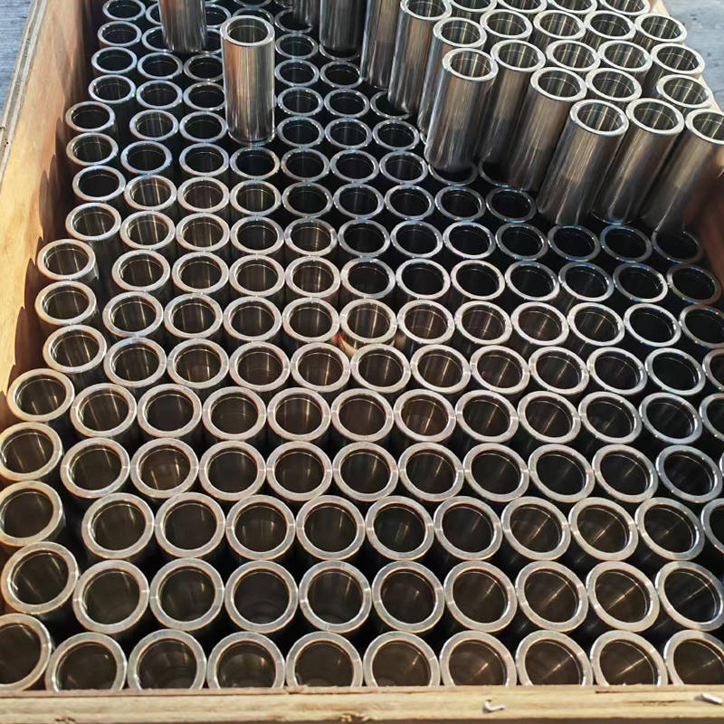
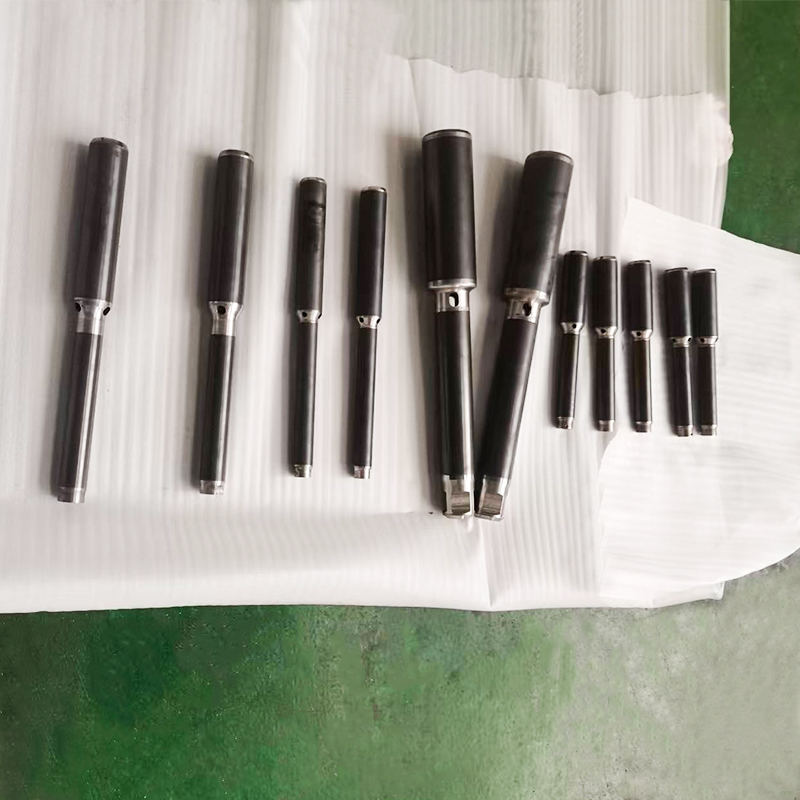
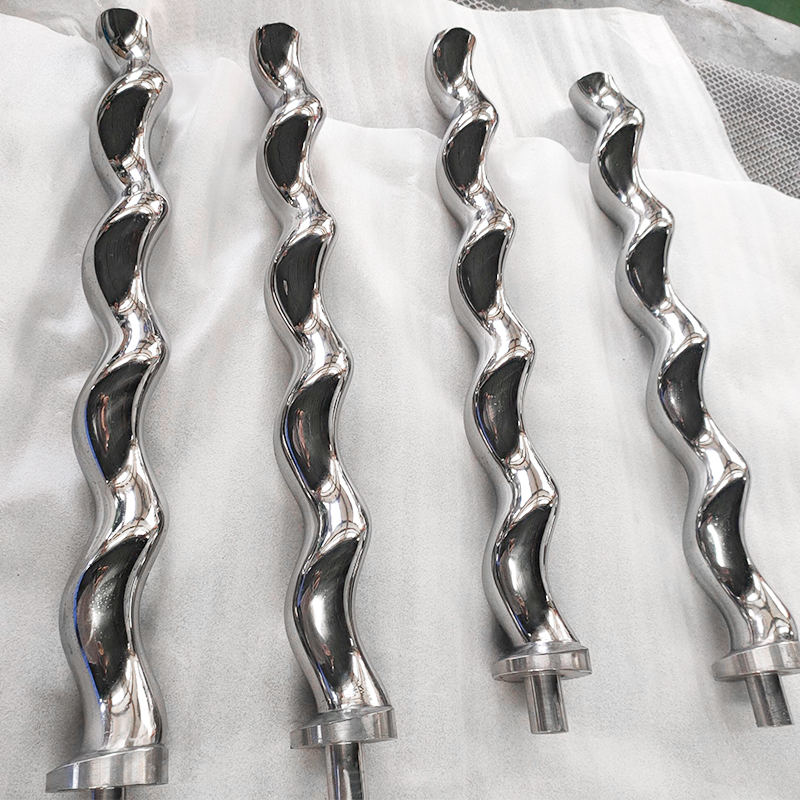
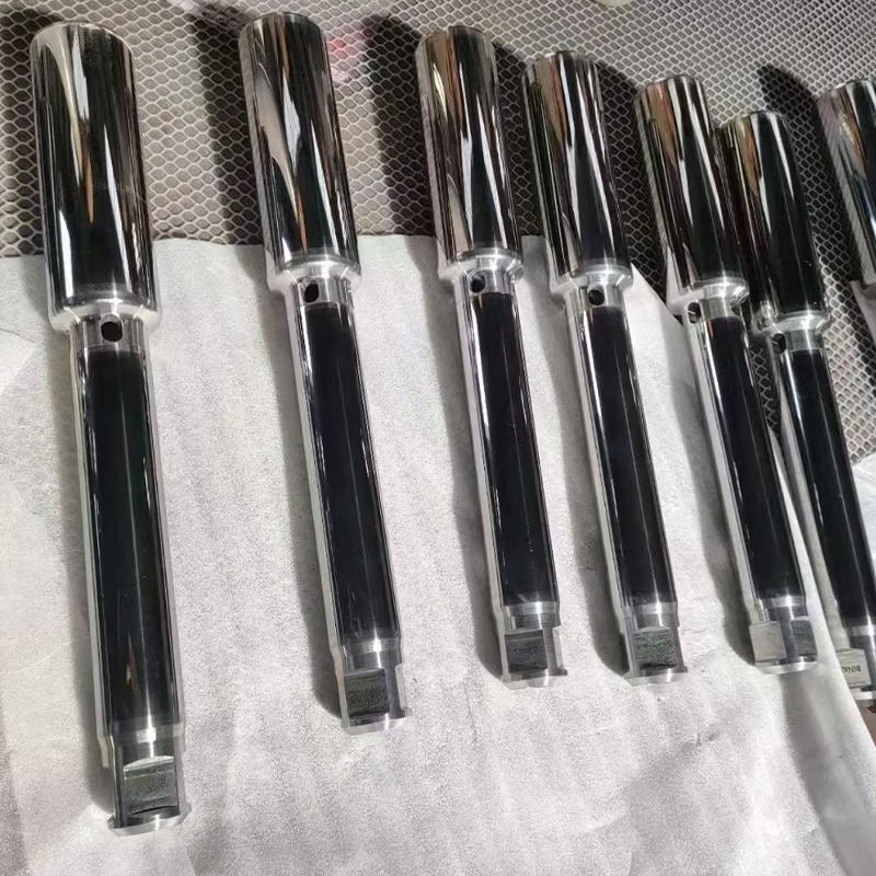 Tungsten Carbide Pump Pole for Pump EquipmentHard wear- and corrosion-resistant pump component for industrial pumps and valves, with custom processing and optional ceramic or tungsten carbide coatings.View Product →
HVOF Compared with Plasma and Flame Spraying
HVOF is not always the answer. Its line of sight requirement, masking effort and consumable cost make it a poor fit for very large parts or low-value components. A quick comparison helps set expectations.
| Process | Particle Velocity | Heat Source | Typical Best Fit |
|---|---|---|---|
| HVOF | 600–1000 m/s | Oxy-fuel combustion | Carbides, erosion and sliding wear, density-critical coatings |
| Plasma | 300–800 m/s | Electric arc | Ceramics and high-melting materials, large areas, complex geometry |
| Flame spray | 50–150 m/s | Combustion, low velocity | Build-up and salvage work, low-cost wear layers |
More detail on how these routes diverge, including gas selection and case examples, is collected in our guide to HVOF and supersonic flame spraying.
Limits and Practical Considerations
Honest HVOF work means acknowledging the constraints. The process is line of sight, so internal bores below a certain diameter require special nozzles or a different method entirely. Masking is labour-intensive on complex parts. Coatings are thin relative to weld overlays, so a part worn past its allowance cannot simply be rebuilt with spray. And the process is loud, hot and dusty — good shops invest heavily in extraction and sound control, not just in the gun.
Quality control deserves the same attention. Bond strength, porosity, microhardness and phase composition are checked on coupons or companion samples, and coating thickness is verified on the part itself. A coating that measures right but has lost its carbide phase will fail early, which is why cross-section microscopy still matters more than a thickness gauge alone.
Bringing the Process to Your Parts
We have spent years running HVOF alongside plasma, arc and wire flame lines, and the lesson repeats: the process is only as good as the preparation and the parameter discipline around it. Our Yancheng facility, which came on stream in 2025 with 20,000 m² of production space, runs supersonic flame spraying as part of a broader thermal spray platform covering pump, valve, petrochemical, die casting, wire drawing and semiconductor components.
If you are weighing HVOF against another coating route, send us the part drawing, the base material and a description of how it fails. We will tell you plainly whether the supersonic flame process is the right tool, and if it is not, we will say so.

 TOP