
 ENG
 English
 عربى
 Español
 中文简体

Ask five engineers what an electrical insulation coating is and you will get five different answers. For a cable designer it is the extruded polymer jacket around a conductor. For a motor lamination supplier it is a micron-thin inorganic film applied on a coil line. For a maintenance team in a plating plant it may be a ceramic skin on a roller shaft that has to stop stray current from travelling where it should not. All of them are right, and that is exactly why the topic gets confusing so quickly.
We spend our working days applying thermal spray coatings to metal parts, and a growing share of that work is electrical rather than purely mechanical. The notes below are what we usually explain to customers who arrive asking for an "insulating coating" without yet knowing which family of coating actually suits their part.
Content
- 1 What an Electrical Insulation Coating Actually Has to Do
- 2 Comparing the Main Insulation Coating Families
- 3 Where Ceramic Thermal Spray Earns Its Place
- 4 When Thermal Spray Is the Wrong Answer
- 5 Semiconductor and Vacuum Hardware
- 6 A Practical Selection Checklist
- 7 Problems We See Most Often
- 8 Wrapping Up
What an Electrical Insulation Coating Actually Has to Do
A coating only counts as insulation if it blocks current in a predictable way across the whole service life of the part. That means the specification has to be written in numbers, not adjectives. The four figures that come up most often in our discussions are:
- Breakdown voltage — the voltage at which the layer fails, usually expressed per unit of thickness.
- Volume and surface resistivity — how well the material resists leakage through its bulk and across its surface.
- Comparative tracking index — how resistant the surface is to carbonised creepage paths when dirt and moisture are present.
- Dielectric constant — relevant when the coating sits inside a field that must be shaped rather than simply blocked.
In real hardware, though, failure is rarely caused by the intrinsic properties of the material. It is caused by a pinhole, an uncoated edge, a thread the spray could not reach, or a coating that has cracked after thermal cycling. Thickness and defect density matter more than the data sheet.
Comparing the Main Insulation Coating Families
The options below are not competitors in a single race; they are tools for different geometries, temperatures and production volumes. Reading across the table is usually the fastest way to rule two or three of them out.
| Coating family | Typical thickness | Main strength | Typical use | Watch out for |
|---|---|---|---|---|
| Epoxy, polyurethane and potting compounds | 0.1–2 mm | Fills complex shapes, cures at low temperature | Electronics, potted sensors, busbars | Upper temperature limit, CTE mismatch |
| Wire enamel and extruded polymer (PVC, XLPE, PTFE, silicone) | 0.2–5 mm | Flexible and cheap at volume | Cables, windings, harnesses | Applies to new wire, not to finished parts |
| Electrical steel insulation coating | 1–5 µm | Punchability, weldability, stacking factor | Motor and transformer laminations | Requires a coil-coating line |
| Ceramic thermal spray (alumina, alumina-titania, zirconia) | 50–500 µm | Insulation combined with wear and heat resistance | Shafts, sleeves, rollers, chamber parts | Porosity, masking, diamond finishing |
| Anodic and plasma electrolytic oxide on aluminium | 5–50 µm | Integral, thin, no adhesion layer needed | Housings, heat sinks, fixtures | Aluminium substrates only |
Where Ceramic Thermal Spray Earns Its Place
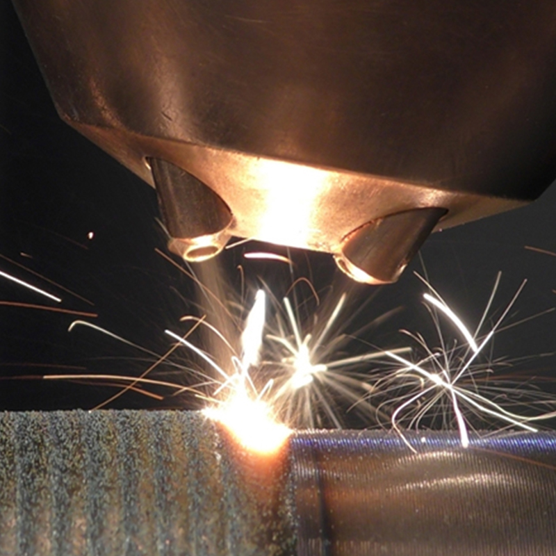
Plasma-sprayed alumina is the workhorse here. Dense sintered alumina can hold well over 15 kV per millimetre, but a sprayed layer is not a sintered one: it is built from flattened droplets, so it carries a small amount of porosity and lamellar boundary structure. In practice we design sprayed dielectric layers around 5 to 15 kV per millimetre and then compensate with thickness, sealing and careful edge coverage rather than promising laboratory numbers.
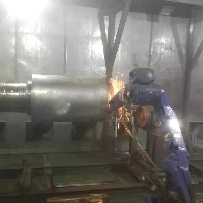
The reason people choose this route anyway is that the coating does two jobs at once. A pump shaft sleeve running in a mildly conductive slurry needs corrosion resistance, abrasion resistance and electrical isolation — and a ceramic layer delivers all three without a separate sleeve or a plastic insert. The same logic applies to rollers in electroplating and anodising lines, guide components near inductive heaters, and insulator rings that also see abrasive dust.
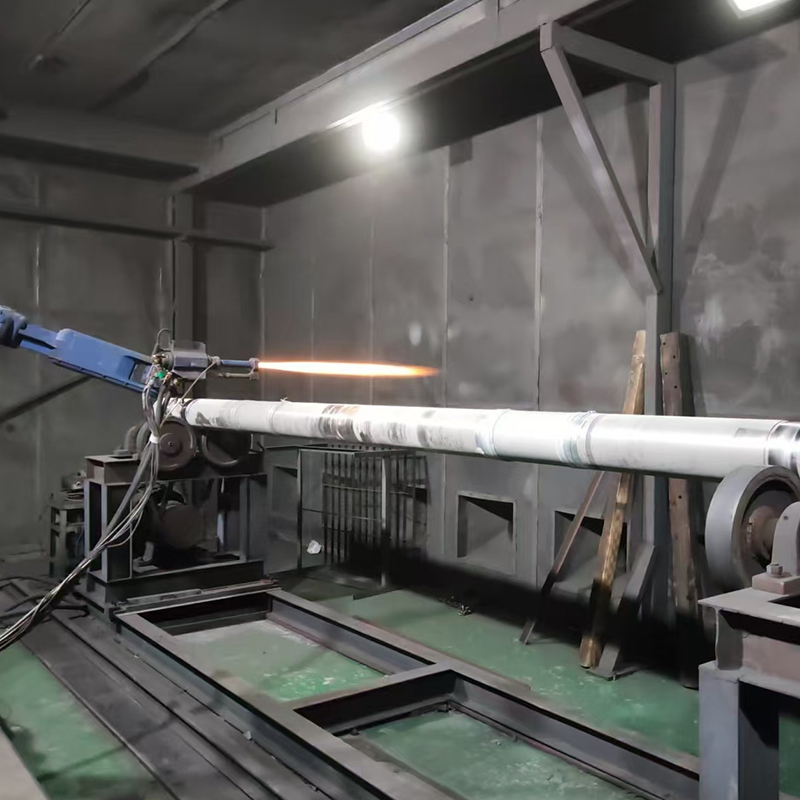
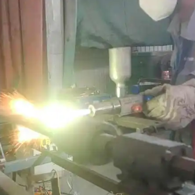
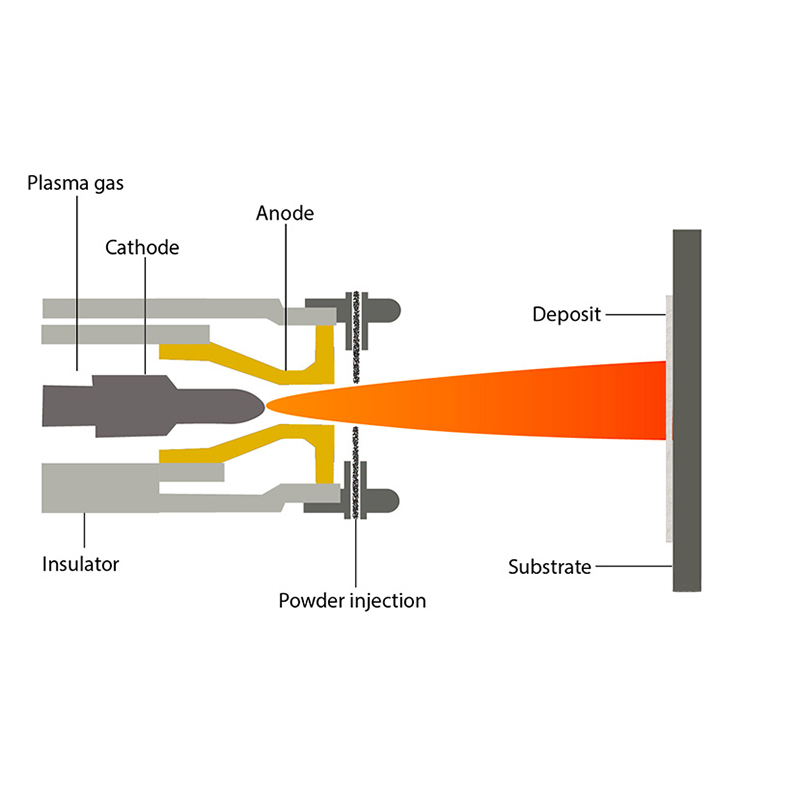 Plasma Spray Coating Service for Ceramic CoatingsThermal spray process using a plasma arc and powder to produce dense ceramic layers for parts that need corrosion, abrasion and electrical isolation.View Product →
Material selection usually starts with alumina for cost and dielectric performance, moves to alumina-titania when some toughness and electrical conductivity in the layer is acceptable, and to zirconia when thermal cycling rather than voltage is the limiting factor. Our overview of ceramic thermal spray coatings goes deeper into how those trade-offs play out across industries.
When Thermal Spray Is the Wrong Answer
Being honest about the limits saves everyone a wasted purchase order. We routinely tell enquirers to go elsewhere when one of the following applies:
- The part is thin, flexible or repeatedly bent — a ceramic layer is brittle and will craze.
- The requirement is high voltage with a strict partial-discharge specification, such as medium-voltage switchgear insulation; that calls for moulded or cast insulation with qualified void-free construction.
- Fine threads, blind holes or internal channels must be insulated uniformly — the spray line of sight simply cannot reach them.
- The part is a large flat panel where a laminated film or anodising is cheaper and adequate.
Semiconductor and Vacuum Hardware
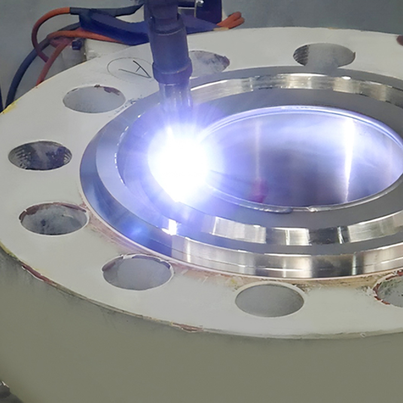
One area where ceramic coatings have become genuinely hard to replace is vacuum and plasma equipment. Electrostatic chucks, chamber walls, cover plates and sealing rings all need a surface that resists plasma erosion while keeping the electrical field where the designer put it. Alumina and yttria-based ceramics are the usual choices, and the difficulty is not the spray itself but the finishing: surface roughness, particle generation, cleanliness and outgassing all have to be controlled before the part goes back into a tool.
 Yttria Coating for Electrostatic Chucks in Etch EquipmentPlasma-sprayed yttrium oxide coating at 100–300 μm for electrostatic chucks, aimed at etch, corrosion and wear resistance in semiconductor etching.View Product →
In these applications the coating is specified together with the cleaning and masking procedure, not separately — a perfect dielectric layer contaminated during handling is still a defect.
A Practical Selection Checklist
When a customer sends us a drawing, these are the questions we ask before quoting. Answering them early shortens the loop considerably.
- State the electrical duty in figures. Applied voltage, allowable leakage current, and whether the coating is a primary barrier or merely a secondary safeguard.
- Define the temperature window including excursions during cleaning, bake-out or shutdown.
- Describe the mechanical environment. Sliding wear, impact, cavitation and thermal shock all change the material choice.
- Identify what must stay uncoated. Bearing seats, sealing faces, threads and datum surfaces need masking, and masking is part of the cost.
- Agree the finishing requirement. As-sprayed ceramic is rough; diamond grinding or sealing changes both the dielectric behaviour and the price.
- Decide the acceptance test up front — hipot, insulation resistance, coating thickness mapping or a destructive cross-section.
Problems We See Most Often
- Rushed surface preparation. Grit-blast profile and contamination control decide adhesion, and adhesion decides whether the layer survives thermal cycling.
- Sharp edges left as machined. A radius of 0.3 mm or more is not cosmetic; it is where dielectric breakdown begins.
- Unsealed porosity. For humid or conductive-fluid service, a sealing treatment after spraying is often the difference between years and months.
- Thickness variation across the part. A coating that measures 300 µm at the centre may read 120 µm at the shoulder, and the weakest point sets the rating.
- Ignoring the substrate. Steel, stainless, aluminium and copper expand differently, and the coating has to be matched to that.
Wrapping Up
Electrical insulation coating is not one product but a family of very different processes, and the right one depends on whether your priority is a flexible conductor, a laminated core, a potted board or a metal shaft that must be hard, hot and non-conductive all at once. Ceramic thermal spray sits at the tough end of that spectrum, and it works best when the electrical requirement is written down alongside the mechanical one.
If you are specifying insulation for parts in power generation, electrolytic processing or heavy electrical equipment, our electricity industry coating solutions show how these layers are applied in practice. Send a drawing with the voltage, temperature and wear conditions marked, and we will tell you plainly whether a sprayed ceramic is the right answer — or point you toward something better suited.

 TOP